Vices
1. OPERATING PRINCIPLE
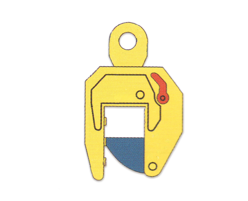
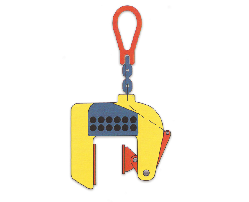
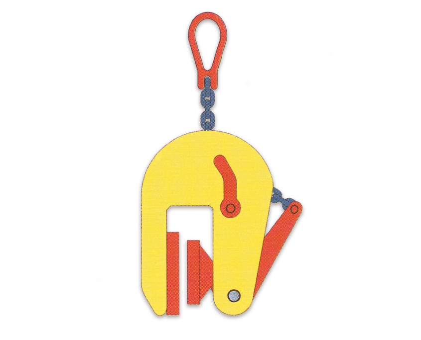
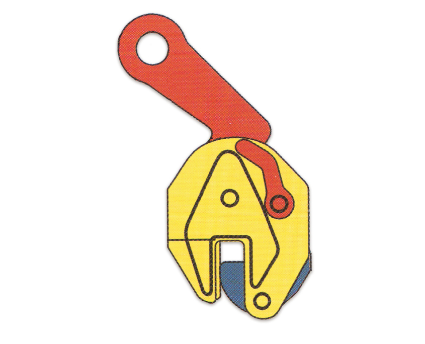
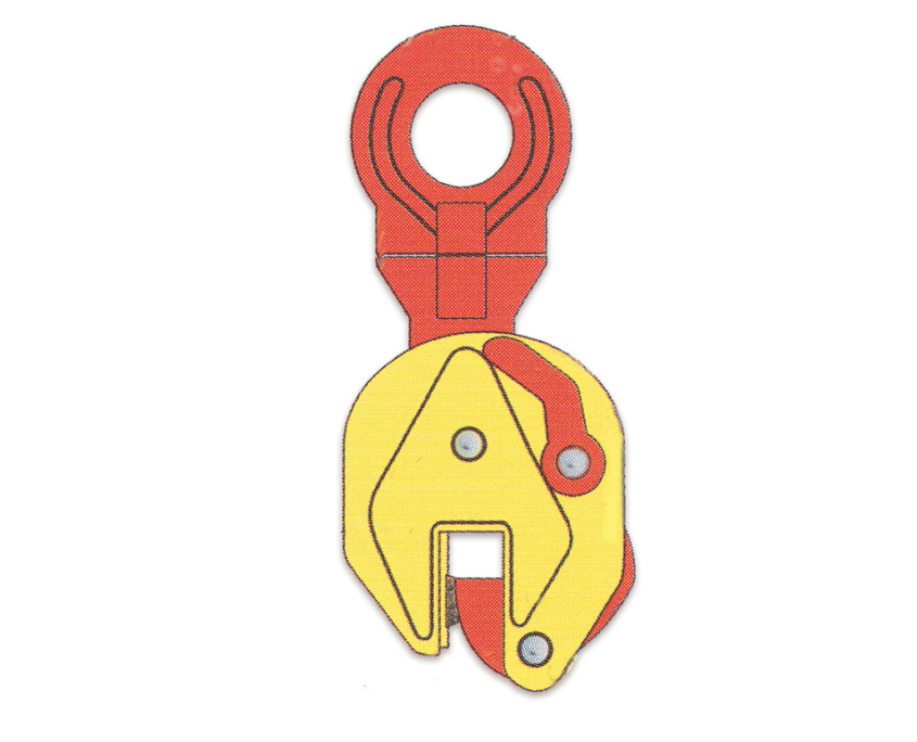
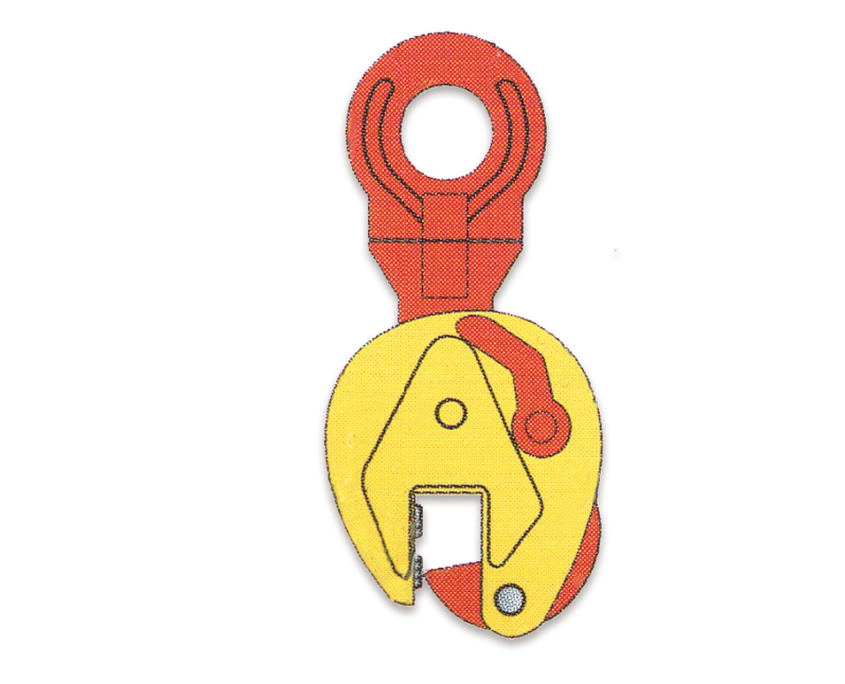
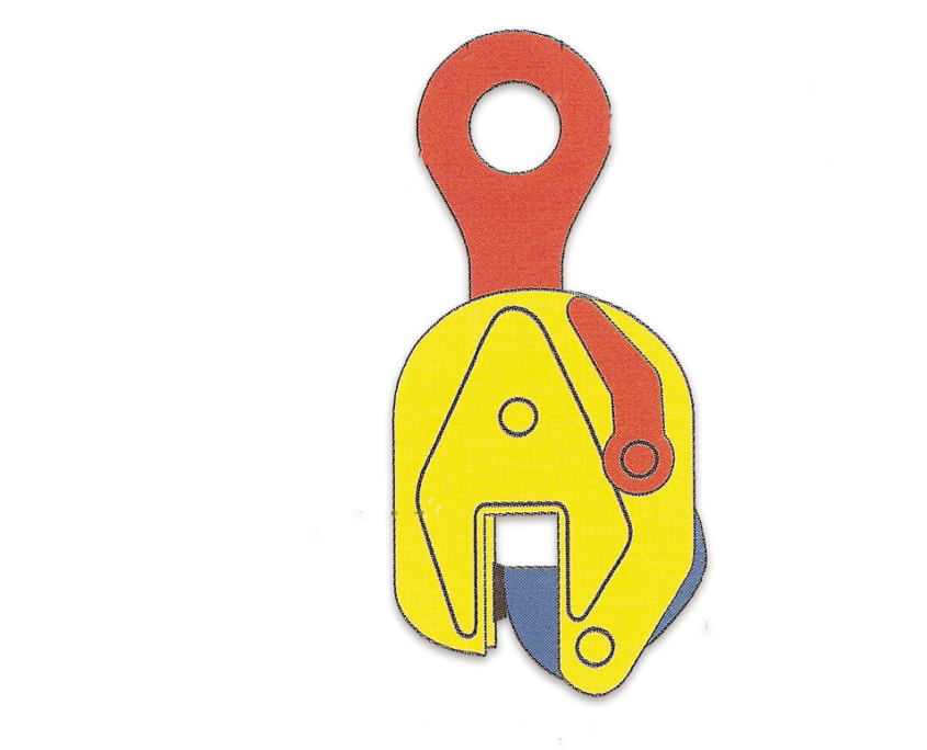
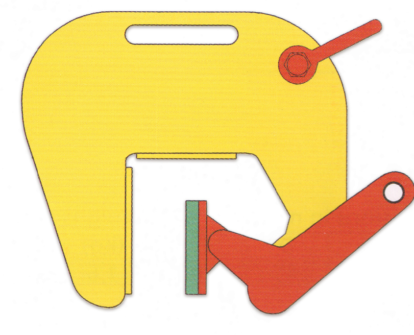
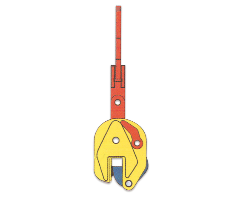
Movintech safety lifting pliers derive their name from the built-in safety mechanism, which consists of a locking device, a tension
spring and a lever. Once the lever is operated, the safety mechanism provides a constant pretensioning of the cam on the steel blade, thus preventing
the gripper from slipping when the lifting force is applied. When a load is lifted, the gripping force on the cam is increased by the weight of the said load
stesso. The safety system also ensures that the gripper does not loosen while the load is being lowered.
Additional information for users of a lifting gripper TSU‐R
The TSU-R lifting gripper is specially designed for lifting and handling of stainless steel blades.
To prevent corrosion due to carbon contamination, this lifting gripper is equipped with stainless steel elements and a nickel-plated body and lever.
Due to these characteristics, the contact area between the gripper jaw and the stainless steel blade no longer needs to be cleaned of carbon steel residue after the lifting operation has taken place.
2. APPLICATION
Movintech lifting grippers have been designed solely for the purpose of lifting and transporting steel blades and structures for which it is possible to place the gripper on
a flat contact point.
The following notes apply to Hardox gripper models: These gripper models are equipped with a specifically developed “hard” segment and pin, so these lifting pliers can be used for lifting blades and/or structures with a maximum hardness of 45 HrC, (429 HB,1450 N/mm2). The models 1 TSHP and 1.5 TSHP are equipped with three pins for optimum grip and are therefore very suitable for lifting “Dutch profiles” (flat-bulb steel bars).
The following note applies to the TSU-R gripper model only.
The TSU-R gripper is only designed for lifting stainless steel products, blades and structures with a flat contact point. In cases where the gripper is
used for lifting carbon steel blades, it can no longer be used for lifting stainless steel blades, without
running the risk of carbon contamination.
Permitted operating positions
Depending on the gripper model, the following operating positions are allowed:
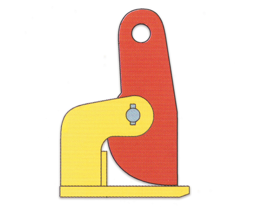
– vertical positions only (TS,TSE)
– from both vertical and horizontal positions (TSU and MP models)
– from all positions (TSU, TSEU, STSU and TSU-R)
Note: A reduced working load limit (WLL) applies when lifting from positions other than vertical.
Also see the load diagram on page x
3. SAFETY INSTRUCTIONS
Safety first and foremost! Ensure your personal safety by first reading the following safety instructions.
Ensure your own safety and continue to enjoy the safety benefits of our product by having the gripper inspected and tested and, if necessary, having it serviced once a year by Movintech or another qualified and reputable mechanical service and repair centre.
Also see Paragraph 8 – Review. Please contact Movintech for more information.
AVOID LIFE-THREATENING SITUATIONS
(also see the section ‘How to use the grippers correctly for
vertical lifting’ on page 37)
– Never operate with an untested or unapproved lifting gripper.
– Always maintain a safe distance during the lifting operation and never remain under the load.
– Do not use a damaged gripper; have it repaired by Movintech or by another qualified and reputable mechanical service and repair centre.
If in doubt, consult your supplier.
– Never lift more than one blade at a time.
– Never lift blades heavier than the WWL, as indicated on the gripper itself and on the test certificate.
– Never lift blades that weigh less than 10% of the WWL as clearly indicated on the gripper and on the certificate.
– Do not lift blades that are thicker or thinner than the jaw opening, as indicated on the grippers and test certificate.
– Be careful when lifting from a non-vertical position.
non verticale. The working load limit (WLL) can be considerably reduced in these lifting situations.
– When using multiple grippers, positioned opposite to each other, provide lifting slings or chains of sufficient length to ensure that
the angle between the slings or chains does not exceed 60 degrees.
– When working simultaneously with a certain number of lifting grippers placed side by side, use a lifting beam (balancer) and lifting slings or chains of sufficient length
to ensure that the lifting handles on the equipment are never subjected to a sideways lift.
– Do not place the gripper on truncated cone or conical shaped parts in the blade or structure to be lifted.
– Remove all grease, oil, dirt, corrosion and scrap from the rolling mill at the point where the gripper is to be attached.
– The hardness of the blade surface must not exceed 37 HrC (345 Hb, 1166 N/mm2). For the TSU-R lifting gripper, note that the hardness of the blade surface must not exceed 30 HrC (283 Hb, 945 N/mm2).
– The vice is only suitable for use in normal weather conditions.

